
10 kV distribution explained: RP, TP, KTP, off-circuit tap changers
What a 10 kV distribution point is, how a package substation differs from a built one, what an off-circuit tap changer does and where in the supply chain…
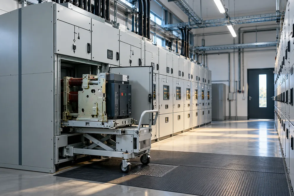
Ukrainian single-line diagrams and grid documents use a set of abbreviations that rarely appear together in English. This page walks the whole chain from the point of common coupling to the workshop board — and answers the question that decides half the budget: connect the storage at 400 V or at 10 kV?
Key parameters
The abbreviations, in the order they appear in the diagram
- RP (РП) — distribution point
- A node that takes one or two incoming 10 kV feeders and splits them across several outgoing ones. No transformer inside: the voltage is the same on both sides. Written as РП-10 кВ in Ukrainian drawings; the nearest English term is a medium-voltage switching station.
- TP (ТП) — transformer substation
- Steps 10 kV down to 400 V. Holds the transformer, the MV switchgear and the LV distribution board. Written as ТП-10/0,4 кВ.
- KTP (КТП) — package substation
- The same substation, but assembled and type-tested in a factory and delivered as one block. The difference is construction, not function: a package substation is craned onto a prepared foundation in a day. Variants: КТПН outdoor, КТПБ in a concrete enclosure, КТПМ pole-mounted, КТПТО with a radial infeed and an enclosure, common on smaller rural sites.
- ShchTP (ЩТП) — LV board of the substation
- The 400 V distribution board inside the substation: incomer, bus coupler, metering, outgoing ways. This is where most storage systems below 1 MW are physically connected.
- ZRU / VRU (ЗРУ / ВРУ)
- Indoor and outdoor switchgear arrangements at 10 kV. Industrial sites are almost always indoor.
- TSN (ТСН) — auxiliary transformer
- A small transformer feeding the substation itself: lighting, cubicle heating, breaker motors, communications. It matters for storage because the BESS cooling and controllers also need an auxiliary supply, and it has to be designed in.
Off-circuit and on-load tap changers
Two ways to trim the voltage ratio, and the choice affects storage directly.
An off-circuit tap changer — ПБЗ in Ukrainian documents, ПБВ in Russian ones — is a winding selector that can only be moved with the transformer de-energised. The standard range is ±2×2.5 %: five positions at −5 %, −2.5 %, nominal, +2.5 % and +5 %. The position is chosen once at commissioning against the measured supply voltage and then left alone for years.
An on-load tap changer (OLTC, РПН) does the same job with a motor drive and an arc-quenching diverter, switching automatically without interrupting supply. Range is typically ±8×1.25 % or ±9×1.78 %.
| Off-circuit (ПБЗ) | On-load (РПН) | |
|---|---|---|
| Switching | de-energised only | on load, automatic |
| Range | ±5 %, 5 positions | ±10–16 %, 17–19 positions |
| Transformer price | baseline | 25–40 % higher |
| Maintenance | effectively none | scheduled drive inspection |
| Typical use | distribution substations 10/0.4 kV | main step-down 35/10 kV |
Why this matters for a BESS: the inverter has a narrow operating voltage window and trips out below roughly −10 % of nominal. On a site with an off-circuit changer and a chronically sagging supply, the tap position must be checked before installation — otherwise the system will trip and the fault will be looked for in the battery rather than in the substation.
Connect at 400 V or at 10 kV?
The fork that decides half the budget. The rule of thumb: below 1 MW, 400 V is usually cheaper; above 2 MW it is almost always 10 kV; in between, both are costed.
| 400 V connection | 10 kV connection | |
|---|---|---|
| Where physically | spare way on the LV board | a cubicle in the RP or in the substation |
| Transformer needed | no | yes, a dedicated step-up for the BESS |
| Sensible power limit | up to 1–1.5 MW | from 1 MW upwards |
| Cable losses | noticeable beyond 100 m | small, the route can be long |
| Added cost | large-section cable, sometimes an LV board rebuild | transformer, MV cubicle, protection relays, design |
| Approval time | shorter | longer, technical conditions needed |
The detail that is easy to miss: at 400 V the constraint is not the inverter but the cable cross-section and the rating of the incoming breaker. An 800 kW system draws around 1,200 A on the low side. That current means busbar or several parallel cables, and beyond a 60–80 m route the cost of copper starts to exceed the cost of a step-up transformer.
Second: a spare cubicle. If the distribution point has none, adding one — with protection and approvals — adds weeks to the programme and its own budget line. It is the first thing worth checking on your own site before requesting a quote.
What the grid side needs, in order
- An up-to-date single-line diagram. The most common delay at the start: the drawing exists but dates from 2011 and half the feeders on it are gone.
- Contracted capacity and the actual maximum over the last twelve months, from bills or the supplier's portal.
- A logged load profile from an analyser on the LV board — at least a week at 1–15 minute resolution. Without it, capacity is a guess.
- Confirmation of a spare cubicle or a spare way on the LV board, plus headroom on the incoming breaker.
- Notification or technical conditions from the DSO, depending on whether power will be exported.
- An updated electrical design: point of connection, protection, metering, earthing.
Items 1–4 can be done in-house within two weeks and determine 80 % of the system configuration. If you already have them, the questionnaire takes about ten minutes and comes back with a specific arrangement.
From the 10 kV network to the workshop
The same site on one diagram. In orange: the two points where storage is actually connected.
Frequently asked questions
What is an RP-10 kV?
What is the difference between a TP and a KTP?
What does an off-circuit tap changer do?
Should a battery system be connected at low or medium voltage?
What if the distribution point has no spare cubicle?
Why does the tap position matter for a BESS?
Figures shown are indicative. We supply the equipment and size the system; design, installation and commissioning are arranged through contractors when needed and quoted separately. Exact sizing follows a load-profile analysis.
Need equipment?
Request a quotation.
Send a model, specification or describe your requirements. We will clarify the configuration, check supply terms and prepare a price quotation.